This post is just another place and time that SolidWorks Sheetmetal has changed my life for the better. Today it made the best part of my day even better. As you know nothing is better than lunch at some greasy spoon buffet with a couple of your co-workers.
We have one of these options really close to our work called the Hong Kong Bistro. This establishment of fine fare always overserves you and take home is 100% guaranteed.

Being as Dangersouly Average as I am, I hate the idea of leaving some behind because the Carryout carton is not large enough.
Total Side Note, Term for SolidWorks Pack and Go in China is Dǎbāo which also can translate to Take-Out… go Figure….
Moving on, if you know the volume of food on your plate, you can use a loft to set the size and shape of your very own carry-out carton

Now for our carry-out box, you *Could* take this shape and covert the body to Sheetmetal and have SolidWorks rip the edges. My issue is that the Eskimo, has real issues making nice clean folds from the covert to sheet metal tool. To save time, we will actually make this part using a MultiBody Technique, and “Wrap” our box around this shape.
Trust me, it will end up being easier this way.
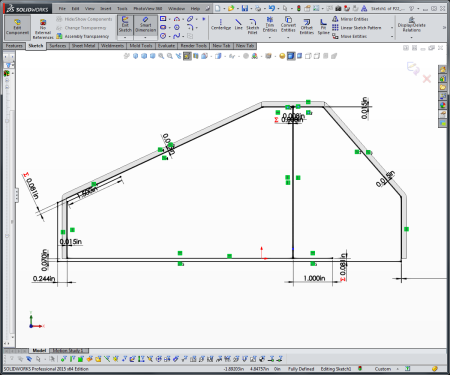
The first actual part of the box is using a Sheetmetal Base Tab / Flange Feature on the bottom face. I convert entities to make sure my container will be the right size if I ever change the base volume.

Next step is wrapping up the sizes of the box. This is just a standard edge flange using one of the edges on the base from the last step.

Now here is where it gets a little tricky, you can use the front face that is highlighted to set the “Angle” of the tab. SolidWorks Sheetmetal will match the angle perfectly if you select parallel to face option.

Then as shown below, you set the “Lenght” of the flange to “up to vertex”. This snaps the length of the flange to be exactly the right length.

The last step is to go in and edit the flange profile. This will let you adjust the actual shape of the sketch to match the trapezoid shape of the box. When it is all done, the flange is the exact wrap onto the base volume!

Now you can do all 4 of these flanges individually, but I typically do two flanges to match the base volume, then mirror my North/South and then East/West Flanges.
Where you can slip up is the next step for the inside folds. As mentioned in Part 1 of this series, for folding cartons and paper materials, you may need to adjust and offset some flange profiles 1/64in at places so they have adequate relief in the corner. You need to have the offset so that you don’t have overlapping geometry.
You need to have these inside folds to keep all the noodle juice from flowing out of the box. If you run the inside tabs without the offset you will eventually get a re-build error. So don’t do this, add the offset.

So, What I do is Dangerously Average, and I Cheat to Win. I create this flange, set it to parallel, but then slightly tweak the angle to get me clearance on one of the flaps! By pulling the flange angle in just inside of 90 degrees you can get the feature to resolve

I don’t want to just ahead too far, but later in the post we will be adding a thin metal wire for a handle. If you don’t make this offset the cut feature will fail, because you will have two material sets that overlap. Even trying to cut with a surface will fail. So just slightly tweak these in please or no food for you!
Here is what the fail will look like:

Adding the top locking tabs is still more patience in keeping that 1/64in offset around all of the edges, but you can get it to fold up!
Start by making two opposite flanges, one with an offset of the material thickness plus the magic 1/64

Then come back and hit a Chamfer on the edges of the flange. using the Select Other function here is super helpful

Now for the Latch on the top. There are a bunch of ways you can do this, but I just started with a sketch. This line I will convert into a Cut Line when exploring the flat-pattern to DXF. This way the German Gal just cuts a slit.

Next, I cut away the extra part of the tab. So I am making this tab not by adding material, but by cutting away what I don’t want. I am able to keep all of the parts lined up because I use the slit sketch to help position my Tab:

With this tab, tomorrow’s microwave mistake is ready to go, I just need a way to carry it out the door. So, let’s get back to that handle. Because you listened above none of the internal flanges overlap so we can cut a clean hole all the way through the box.

And you can test it out to make sure everything unfolds just right. If the flat-pattern fails, go back and check your magic 1/64’s. The slit sketch should also move as too.

The next part is back to basics, By using the holes, I was able to create a sweep to make the wire.

For the actual sketch, I did convert the handle to a fit spline

The fit spline will force the sketch into one continuous sketch and help smooth it out a little bit more. The biggest reason why to convert to a fit spline is that SolidWorks will calculate the length of the handle, so I know just how much wire to cut.

Some might question putting in that much work for a little Take-Out Food? It’s all right to judge, but then again if you do maybe you are not Dangerously Average Enough!


