You read that right. SolidWorks Sheetmetal has changed my life. So much so, that I am starting a whole series of posts just to keep you up to date on how sweet SolidWorks Sheetmetal is, and how much it is actually making my life better.
But before I show a bunch of technical information, you might need some context first. See at work we have his German Eskimo that forces me to be better. As you can see, she is a pretty serious gal.

Wait, sorry wrong picture, here she is:

This is a Kongsberg / Esko cutting table and is designed to cut a huge variety of materials, from plastics to Folding Carton (Like Index Cards), to Corrugate (Cardboard), and Foam Boards (UltraBoard, GatorBoard). It is a lot like a Cricut or Silhouette cutting machine that your neighbor takes to scrapbooking parties over at Archivers. The difference is that this machine is not layering a bunch of 2nd rate clip art into a brag book, and then stuffing down your throat how much better of a parent they are.
No bias or anything, but the Kongsberg is just an industrial workhorse that has a 5ft X 10ft bed.
Its cuts a huge variety of materials, from plastics to Folding Carton (Like Index Cards), to Corrugate (Cardboard), and Foam Boards (UltraBoard, GatorBoard). But all of these materials are different. Critically they do not bend like traditional metal materials that SolidWorks normally manages.
That is the crux of this post. This post is all about the methodology I used to create custom gauge tables for SolidWorks Sheetmetal. Turns out that by following the steps outlined below, I now have (4) custom gauge tables that I can use for pretty much any flat paper stock. As you follow along, keep in mind, these techniques are not 100% accurate but will be sufficient for most of what I am doing, and hopefully will do what you need as well.
The first step to making these custom tables was to identify and understand how much deformation/stretch/shrink each of the materials had.
I started by making a quick Go/No-Go Gauge pictured below to help measure the lengths of the parts after they were bent. I cut this out on the table and checked that cut dims were accurate.

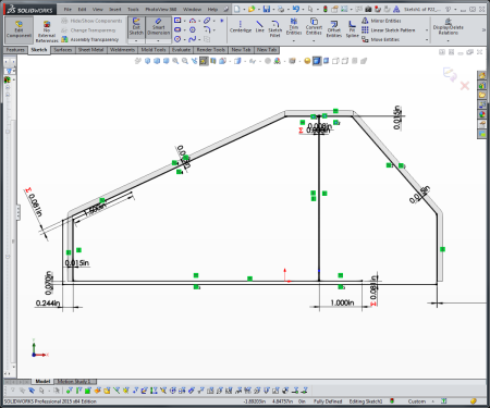
Once the Check Gauge was complete, I need a small sample that I could make with a couple of bends. I settled on this Try-Angle design. The flats or bend line locations were at 100mm so that I could quickly try to guess what the bend length was. Here is that part:

After cutting several samples of the Tri-Angle Gauges. I used the Go/No-Go Gauge and calipers to estimate the formed length of each part and averaged these out. So for 12pt Folding Carton, I ended up with a table that looked like this:

I repeated these steps for all of the other “Paper Stocks” and got this table:

A Couple quick things to mention here:
First I calculated the K-Factor using some formula that Google gave me. I picked K-Factor over Bend Allowance / Bend Deduction as the K-factor required less work & one K-factor will control the entire table.
Next K-Factor sucks with these materials because K-factor is based on the expectation for the material to stretch in the bending process. Paper-based materials won’t be held down to those rules and effectively have NO stretch for all intents and purposes, the bend radius is zero.
To get tables that are accurate enough to use, I had to create multiple tables for different paper stocks. Normally your gauge table could have a whole family of thickness and size. For paper, due to the non-stretch and zero bend radius, I needed more tables to cover all the material thicknesses.
I ended up averaging my K-factor for the material family to get me something workable. For the tables, the bend radius was also set to .001 because anything more felt like too much and anything less felt like I was not doing justice. The end product gives me a set of tables for corrugated that do look out of wack for the larger B/C Double Wall material, but it still works for *most* things.
Once I had these values, I copied the stock SolidWorks Sheetmetal Gauge Table and renamed it, and plugged in the new values.
With some additional testing, both my co-workers and German friends were comfortable with the results, and the tables were approved for production.
With this success at my back, I moved to the other materials and mediums that our Eskimo can cut. Specifically thin plastic materials like PETG, or Rigid Vinyl. Lastly, I followed it up with heat-bending materials, which included things like Expanded PVC and PETG and Acrylics in the Heat bent calculation stuff. Now I am left with (4) Tables that look something like this:

So that was the hard part, but it works. I do recommend that you publish these tables to a network location so that if your computer crashes you don’t have to re-do all of the work. I supposed if you were feeling generous, you could share it with other people as well.
Now with the tables set up, lets take a quick look at using them in a sheetmetal part. Here I sketched a “Rat Trap/Roll Up” that folds back on itself. Typically I have had a lot of success keeping about a .01in the gap so that the features don’t fail.

Then Pick your Table, and Gauge:

From here pick your actual Table and material:

When using the Gauge Table, SolidWorks will use the Table to define the material thickness and bend parameters. All you have to do is enjoy your part!

I suggest you take a look at making custom SolidWorks Sheetmetal Gauge Tables. It has been a huge help in keeping my flat-patterns and overall work performance Dangerously Average.


